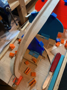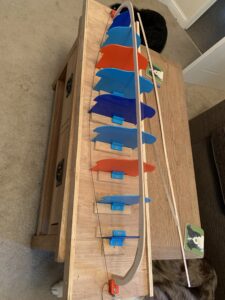
Strakes… slow but steady !

I think I’m starting to get to grips with the strakes now, having gradually figured out their shape, how they change as you get further from the keel etc…

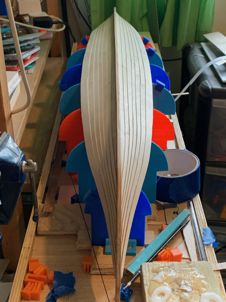
I’m nearly at the half way stage now with 7 of the 16 strakes in place on each side. The hull is starting to take on the shape and lines. Each strake has to be shaped to form the overlapping shapes at the bow and stern where they are nearly vertical. At the same time they need to allow the bottom of the hull to be almost flat for at least the first 8-9 strakes.


The first strakes used a straight edge from bow to stern, utilising the natural flex in the wood to form the correct shape. As I’ve moved further from the keel though I’ve needed to add a curve to the edge closest to the keel. Until the centre of the hull approaches the water line, the curve will need to increase for each strake.

I’m tracing the outline of each strake as I complete them so I can easily make replacements. I will probably end up digitising them once I’m happy with the final hull.
Strakes, part 1

First strakes in position
First strakes attached and held in position by clips.

It’s been a while since I made any real progress on building the boat, having spent a lot of time experimenting and trying different options for the strakes.

The shape of the strakes has been difficult to determine as it’s essentially their shape that determines the contours of the boat. They are shaped so, as they bend to meet at the bow and stern they naturally form the shape of the boat. Turning flat pieces of wood into a contoured shape.

I finally came up with a series of shapes that I’m happy with and took the major step of actually attaching the first strakes to the keel. As I add more and more strakes I’ll either be rewarded with the correct shape if I get it right or realise I got it wrong and have to start again !

Second strakes added to both sides

So, right now I’ve added the first two strakes on both sides and, so far at least, it looks to be forming the correct shape in line with the plastic guides. I’ve designed and printed a number of different clips to help hold the strakes in place while the glue dries so the 3D printer has been a big help with that.

Each strake is slightly different as, as well as forming the hull shape as it’s bent into position it also has to form the distinctive shapes at the bow and stern. The first few strakes overlap each other in such a way that they only form part of the end shapes. Later strakes will all go to the ends.

Former finished ?

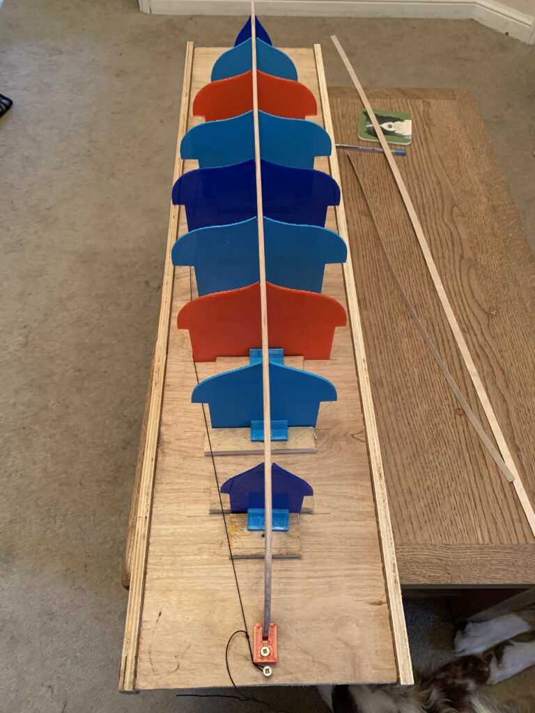
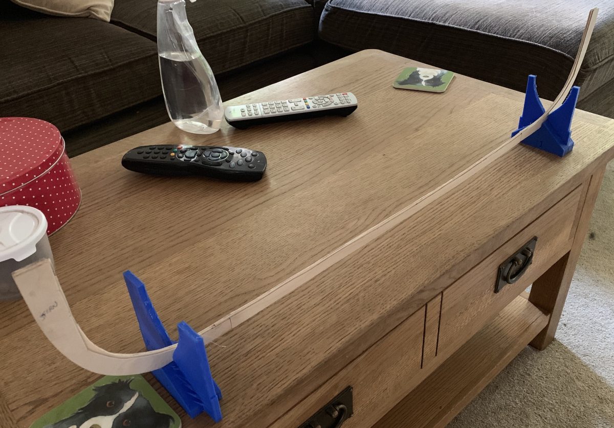
Updated former/guide with the keel in position.

After starting to lay down the keel and experimenting with the freshly cut strakes I realised that the wooden guides for the former weren’t quite right. I was also having issues with the base warping along it’s length which was never going to be a good thing !

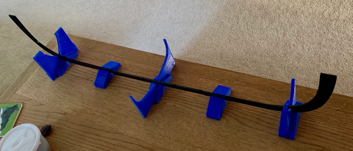
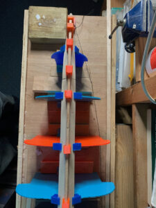
So, I opted to created 3D models of each section/guide and printed them out to improve accuracy and consistency. By using printed plastic clamps I also have a bit more leeway for adjusting the final positions of the formers vertically and horizontally to make sure everything is lined up as accurately as possible.

You can’t really see from the picture but each guide also has grooves that mark the position of the bottom of each strake which should help me to reproduce the original spacing/positioning. The black elasticated string was used initially to align the guides horizontally and may be useful for guiding the strake position as I build it up.

I have some additional layers to add to the keel to form the “T” to help support the first strake as it joins the keel. I can then start to add the first strake.

Plank Cutting

At 1:24 scale the planks/strakes that were used in the original (approx 10 inches wide by 1 inch thick) scale to approximately 10mm x 1mm. I’m using beech ply for the strakes as it’s both flexible and relatively tough.

To aid in cutting the basic planks that will act as a starting point for forming the strakes I have modified a design of a tool that was created for cutting balsa planks. Desiging and 3D printing the tool has allowed me to accurately cut planks from sheet ply.

I’ve published my design for the tool here…
https://www.thingiverse.com/thing:4255410
Where it can be downloaded and 3D printed. A video of the tool in operation can be seen below…

Former created

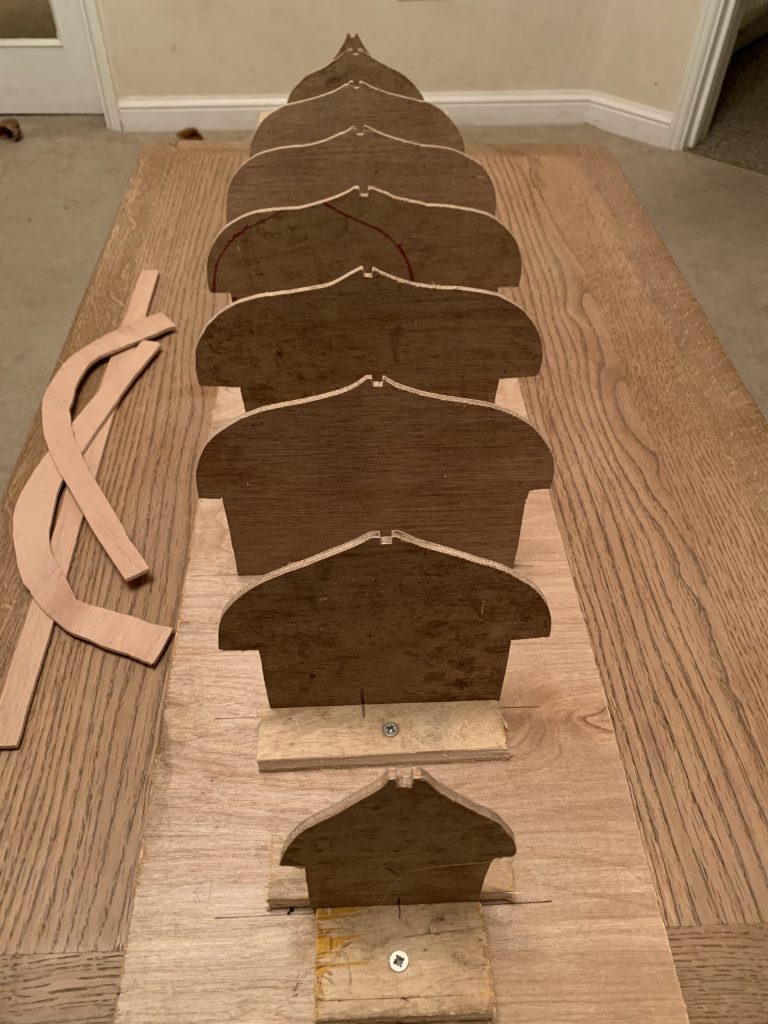
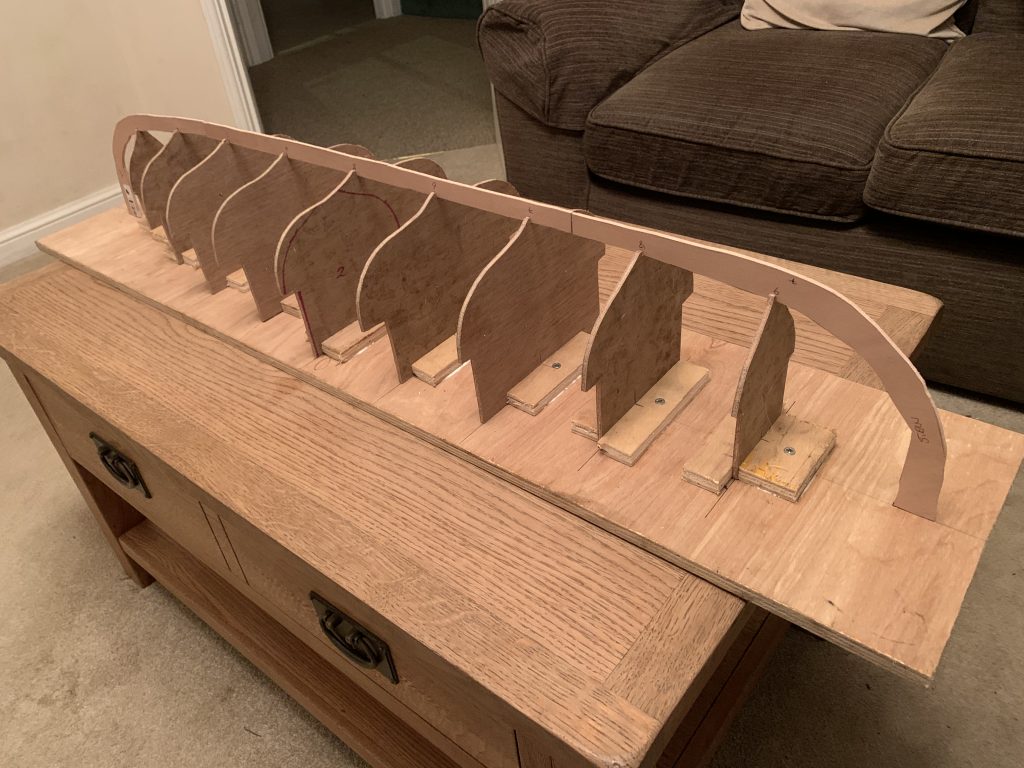
1:24 scale former and guide

The first steps in preparation for the construction – creating a guide/former that will hopefully help keep everything aligned during the construction process.

I’ve cut a guide for each of the 9 datum points detailed in the original drawings and positioned them along the centre datum. By lifting the guides off the board the ends of the bow and stern will sit directly on the board.

The shaped pieces of wood to the left of the base are the first sections of the keel that I’ve roughed out. The picture below shows the three sections resting on the former in approximately the correct position…

First keel sections positioned on the guide.

Fresh start

1:24 representation of the keel with the section markers

I’ve been putting off shaping and adding strakes to the keel while I’ve re-evaluated the project in the last few months. I’ve slowly come to the conclusion that the previous choice of scale (1:32) wasn’t going to be a practical option.

Although 1:32 has it’s benefits and would work well as a static model I’ve been looking at what will be involved to integrate RC components into the build to control the sail and rudder and, at 1:32, I don’t think there is enough space to hide the components.

So… I’ve ditched the 1:32 parts and started creating a new keel at 1:24. I’ve also decided to create a wooden former that will act as a workspace while keeping the keel and strakes true. I know a lot of people build these ships onto a frame, using a technique that was common in later use. Viking ships were built as a shell up to and above the waterline. The internal frames were then added and tied to the strakes.

I’d like to use the same technique with my model but will use a former as a guide while the shell is built. The original boats were built from the keel up and stone/rock was used to maintain the shape of the shell (along with the shape of the strakes and the natural bend of the wood as a result). I’m expecting to build mine upside down and use the former to hold the shape while I add the strakes.

Keel roughed out

I’ve now completed a rough layout of the keel. The keel is approximately 5.6mm thick at 1:32 scale and to simplify construction somewhat I’ve used ply sheeting. One sheet of 4mm ply makes up the core of the keel, sandwiched with two sheets of 0.8mm.

Creating it this way allows for my lack of woodworking tools as it allows the steps for the planking to be incorporated. It also, I think, adds to the strength of the keel which was originally a 7 inch by 14 inch section of oak.

As with the original, the keel is constructed in 3 sections, the keel itself in the centre and the the bow and stern sections at each end.

Now the keel is roughed out I can start experimenting with the methods for shaping and adding the planks. The lower planks, in particular, will need to be mocked up in cardboard to try and get the planks to form the curves of the hull as they are added.

First steps…

All Viking ships begin with the keel and my model is no exception to that rule ! I’ve settled on a scale of 1:32, hopefully large enough to faithfully be able to model the components but small enough for transport/storage.

To aid in building the hull and ensuring symmetry and alignment, I cheated somewhat by creating and printing a 3D model of the basic keel shape and stands that will hold the keel securely.

The keel design, and the profile guides added to the stands, were taken from the available online plans of the original ship. I’ve had to use a conglomeration of different plans as many of them are not properly to scale/ratio and there are some differences between them so I’ve had to make some compromises. Rightly or wrongly I’ve chosen the deepest of the keels that appear in the plans, hoping that that will give a better performance and decrease lee drift.

For the plastic template I’ve created a very wide stem at both ends to give some scope for adjustment in the wooden version. The outer curve is correct but the inner is a lot deeper that the final version will be. I’m undecided yet on the stem design, I may try and make the top of the stems removable so I can swap between different designs. The “classic” interpretation of a dragon’s head seems to be falling out of favour with researchers and there is some evidence that the stem figures were removable.

I may end up creating 3D models/templates of other parts of the construction to help visualise and test the construction. I’ll upload the CAD files when I’m happy that they represent final versions.